Full wave precision rectifier pdf
GET pdf × Close Log In. Log In full wave precision rectifier. Download. full wave precision rectifier. Uploaded by. Omid Alborzi. Loading Preview. READ PAPER. GET pdf × Close Log In. Log In with Facebook Log In with Google. or. Email: Password: Remember me on this computer
16/03/2005 · I have added a copy of an article from the 11/25/82 EDN (where I first saw the two-OpAmp FW Rectifier described) to “FullWaveRectifier.pdf” on the S.E.D/Schematocs page of my website.
proposed circuit performs positive half-wave, negative half-wave, positive full-wave, and negative full-wave rectification into a single circuit. The current-mode technique has been employed to provide the high-precision
important notice for ti reference designs have
or two resistors. Here, neither voltage nor current biasing Abstract—In this paper a precision full-wave rectifier of minimal configuration is presented.
www.electronics.dit.ie Precision Rectifier Circuits An Application: Measuring AC voltage For a sine wave input with peak value Vp, the output of the
Two op-amps can be combined to produce a full wave rectifier also. This is not some form of perfect power rectification – its use is limited to low power signals.
Precision Rectifier Circuit for CT Signal Conditioning 144 Applications H 3500 Scarlet Oak Blvd. St. Louis MO USA 63122 V: 636-343-8518 F: 636-343-5119
A New Precision Peak Detector/Full-Wave Rectifier 73 value of the input sinusoidal signal. Due to the wave- forms of a power system, voltage and current are sinu-
This paper describes a simple and versatile current-mode full-wave precision rectifier circuit using AD844 from Analog Devices. The proposed scheme avoids the use of closely matched resistors and matched current mirrors. The circuit is easy to design and construct from readily available low-cost
today of hi ghly stable, nearly pure sine-wave power sources and precision linear operational devices, the situation has changed. For some ac-dc transfer work such as amplitude monitoring [1],1 the average a-c responding systems to be described can have a su peri ority of precision over rms converters. In addition, the wide usage of average responding instruments such as digital voltmeters
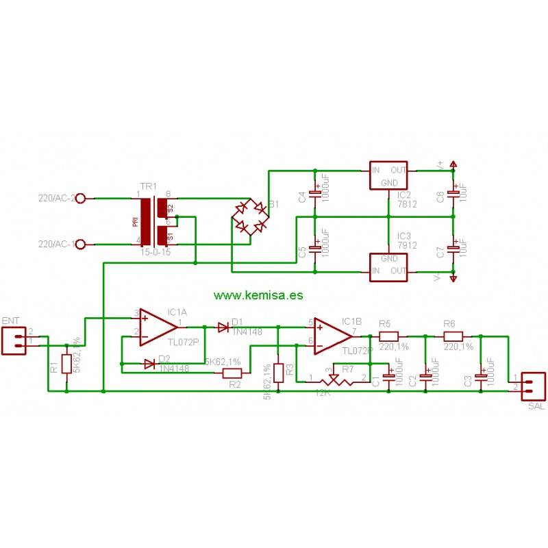
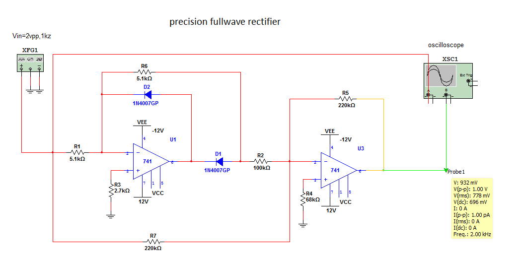
The circuit shown figure 7.2.4 is an absolute value circuit, often called a precision full-wave rectifier. It should operate like a full wave rectifier circuit constructed with ideal diodes (the voltage across the diode, in forward conduction, equals 0 volts). The actual diodes used in the circuit will have a forward voltage of around 0.6
In particular, the following very simple half-wave rectifier circuit appears to work just as well as the circuit above: simulate this circuit – Schematic created using CircuitLab The lower output impedance of the op amp in this circuit means that droop is acceptable with a 1 nF capacitor.
PrecisionFWRectifier — Overview Objectives: To design full wave precision rectifiers using op-amps. Pre lab questions: 1. What is the difference between an ordinary rectifier and a precision rectifier …
Full-Wave Current-Mode Precision Rectifiers Using Unity

Precision full wave rectifier + octave up diypedals
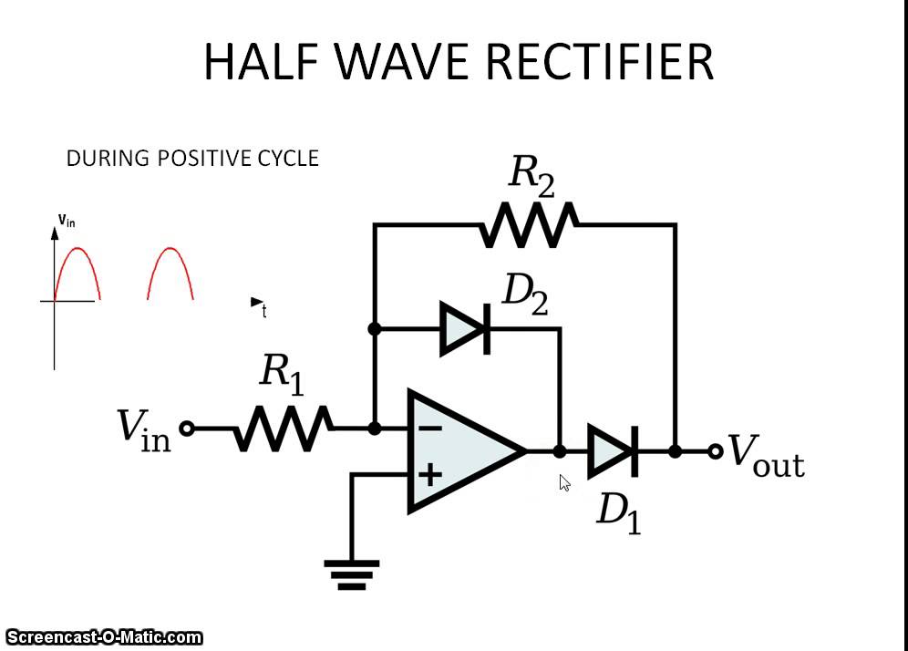
Precision half – wave Rectifier The diode rectifier circuit and its associated voltage transfer characteristic curve are shown on Figure 1(a) and (b). Figure 1. Diode rectifier circuit (a) and voltage transfer curve (b) The offset voltage Vd is about 0.7 Volts and this offset value is unacceptable in many practical applications. The operational amplifier and the diode in the circuit of Figure
Abstract—This paper present high-precision half-wave rectifier circuit in dual phase output mode by 0.5 µ m CMOS technology, + 1.5 V low voltage, it has received input signal and sent output
Precision Full-Wave Rectifier Using Two DDCCs [PDF] Montree Kumngern Circuits and Systems (CS) , 2011, DOI: 10.4236/cs.2011.23019 Abstract : A new precision full-wave rectifier employing only two differential difference current conveyors, which is very suitable …
For negative inputs, the first section operates as a closed-loop inverter (A=-1) and the second stage is simply a buffer for the positive output. When the input signal is positive, the first opamp output remains saturated near ground and the diode becomes high-impedance, allowing the signal to pass directly to the buffer stage non inverted.
Figure 9 shows a precision full-wave rectifier with DC smoothing. As shown, V O is a DC voltage equal to the rms voltage of V IN provided that V IN is a sine wave.
Precision Rectifier – Download as PDF File (.pdf), Text File (.txt) or read online. precision full wave rectifier
1/11/2015 · EE 201 rectifiers – 13 Full-wave peak rectifier Placing a capacitor in parallel with the load, turns the circuit into a full-wave peak rectifier.
Precision Full-Wave Rectifier, Dual-Supply TI Precision Designs Circuit Description TI Precision Designs are analog solutions created by TI’s analog experts. Verified Designs offer the theory, component selection, simulation, complete PCB schematic & layout, bill of materials, and measured performance of useful circuits. Circuit modifications that help to meet alternate design goals are also
arXiv:1205.4604v2 [physics.gen-ph] 20 Apr 2013 TRANSISTOR AS A RECTIFIER RajuBaddi NationalCenterforRadioAstrophysics,TIFR,Ganeshkhind,P.O.Bag3,PUNE411007.
SERBIAN JOURNAL OF ELECTRICAL ENGINEERING Vol. 5, No. 2, November 2008, 263-271 263 Full-Wave Current Conveyor Precision Rectifier Slobodan R. Djukic1
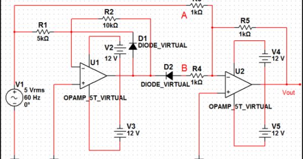
Full Wave Precision Rectifiers. Figure 4 shows the standard full wave version of the precision rectifier. This circuit is very common, and is pretty much the textbook version.
26 ISSN 1392 – 1215 ELEKTRONIKA IR ELEKTROTECHNIKA. 2003. Nr. 7(49) T 171 MIKROELEKTRONIKA Full-Wave Current-Mode Precision Rectifiers Using Unity-Gain Cells
Unlike the half-wave rectifier, the full-wave rectifier can utilize both the negative and the positive portion of the AC input voltage. In order to achieve a unipolar output, the negative portion of the sinusoidal waveform must be inverted. This can be accomplished …

Talk:Precision rectifier Jump to navigation Jump to search So I dunno. The name is fine, I guess. Plus we have to differentiate between precision half-wave and full-wave rectifiers. — Omegatron 17:57, 4 December 2005 (UTC) Vin arrows.
The full wave rectifier circuit consists of two power diodes connected to a single load resistance (R L) with each diode taking it in turn to supply current to the load.
Bancha Burapattanasiri et al /International Journal of Engineering and Technology Vol.1(2), 2009, 46-49 46 Full-Wave Rectifier Circuit Responding in Linear
LT1078 Absolute Value Circuit (Full-Wave Rectifier
Design a full-wave rectifier with LC filter to provide 10 V dc at 100 mA along with maximum ripple of 2%. The frequency of input voltage is 50 Hz. Determine the ripple factor of the LC filter. Solution: 10. Figure 4.34 is the output waveform of a half-wave rectifier with
Single Phase Full Wave Controlled Rectifier Figure below shows the Single phase Full Wave Controlled Rectifiers with R load • The single phase fully controlled rectifier allows conversion of …
A novel full-wave precision rectifier circuit employing a single EXCCII, a MOS switch and one resistor is proposed. The proposed voltage-mode full-wave precision rectifier is simple and operates
A Novel Current-Mode Full-Wave Rectifier Based on One CDTA and Two Diodes Precision rectifiers are important building blocks for analog signal processing. The traditional approach based on diodes and operational amplifiers (OpAmps) exhibits undesirable effects caused by limited OpAmp slew rate and diode commutations. In the paper, a full-wave rectifier based on one CDTA and two Schottky
M. KUMNGERN 129. voltage ranging from –1 V to 1 V of the input voltage. The magnified zero crossing of . Figure 4. is shown in . Figure 5. In this figure, the blunting region (b) is found
This circuit is a good introduction to the full-wave precision rectifier circuit, although its operation there is a bit more difficult to understand than it is here. Question 9 Determine the output voltage of this circuit for two different input voltage values: +4 volts, and -4 volts.
Output voltage of a full-wave rectifier with controlled thyristors Rectifiers are also used for detection of amplitude modulated radio signals. The signal may be amplified before detection. – fitbit alta hr user manual
full wave precision rectifier omid alborzi Academia.edu
Precision Rectifier Circuit for CT Signal Conditioning

precision full wave recitifier on a chip? Electronics Forums
A Novel Current-Mode Full-Wave Rectifier Based on One CDTA
Precision Rectifiers educypedia.karadimov.info
precision FULL WAVE RECTIFIER datasheet & applicatoin

freestyle precision neo user manual –

HIGH-PRECISION HALF-WAVE RECTIFIER CIRCUIT IN DUAL PHASE
Full-Wave Rectifier Circuit Responding in Linear Wide
Precision Full-Wave Rectifier Using Two DDCCs [PDF] Montree Kumngern Circuits and Systems (CS) , 2011, DOI: 10.4236/cs.2011.23019 Abstract : A new precision full-wave rectifier employing only two differential difference current conveyors, which is very suitable …
Design a full-wave rectifier with LC filter to provide 10 V dc at 100 mA along with maximum ripple of 2%. The frequency of input voltage is 50 Hz. Determine the ripple factor of the LC filter. Solution: 10. Figure 4.34 is the output waveform of a half-wave rectifier with
A novel full-wave precision rectifier circuit employing a single EXCCII, a MOS switch and one resistor is proposed. The proposed voltage-mode full-wave precision rectifier is simple and operates
Precision half – wave Rectifier The diode rectifier circuit and its associated voltage transfer characteristic curve are shown on Figure 1(a) and (b). Figure 1. Diode rectifier circuit (a) and voltage transfer curve (b) The offset voltage Vd is about 0.7 Volts and this offset value is unacceptable in many practical applications. The operational amplifier and the diode in the circuit of Figure
today of hi ghly stable, nearly pure sine-wave power sources and precision linear operational devices, the situation has changed. For some ac-dc transfer work such as amplitude monitoring [1],1 the average a-c responding systems to be described can have a su peri ority of precision over rms converters. In addition, the wide usage of average responding instruments such as digital voltmeters
Bancha Burapattanasiri et al /International Journal of Engineering and Technology Vol.1(2), 2009, 46-49 46 Full-Wave Rectifier Circuit Responding in Linear
M. KUMNGERN 129. voltage ranging from –1 V to 1 V of the input voltage. The magnified zero crossing of . Figure 4. is shown in . Figure 5. In this figure, the blunting region (b) is found
Precision Rectifier Circuit for CT Signal Conditioning 144 Applications H 3500 Scarlet Oak Blvd. St. Louis MO USA 63122 V: 636-343-8518 F: 636-343-5119
www.electronics.dit.ie Precision Rectifier Circuits An Application: Measuring AC voltage For a sine wave input with peak value Vp, the output of the
Single Phase Full Wave Controlled Rectifier Figure below shows the Single phase Full Wave Controlled Rectifiers with R load • The single phase fully controlled rectifier allows conversion of …
SERBIAN JOURNAL OF ELECTRICAL ENGINEERING Vol. 5, No. 2, November 2008, 263-271 263 Full-Wave Current Conveyor Precision Rectifier Slobodan R. Djukic1
arXiv:1205.4604v2 [physics.gen-ph] 20 Apr 2013 TRANSISTOR AS A RECTIFIER RajuBaddi NationalCenterforRadioAstrophysics,TIFR,Ganeshkhind,P.O.Bag3,PUNE411007.
A Novel Current-Mode Full-Wave Rectifier Based on One CDTA and Two Diodes Precision rectifiers are important building blocks for analog signal processing. The traditional approach based on diodes and operational amplifiers (OpAmps) exhibits undesirable effects caused by limited OpAmp slew rate and diode commutations. In the paper, a full-wave rectifier based on one CDTA and two Schottky
A New Precision Peak Detector/Full-Wave Rectifier 73 value of the input sinusoidal signal. Due to the wave- forms of a power system, voltage and current are sinu-
The full wave rectifier circuit consists of two power diodes connected to a single load resistance (R L) with each diode taking it in turn to supply current to the load.
Current-mode precision rectification International
Full-Wave Current-Mode Precision Rectifiers Using Unity
A New Precision Peak Detector/Full-Wave Rectifier 73 value of the input sinusoidal signal. Due to the wave- forms of a power system, voltage and current are sinu-
Precision half – wave Rectifier The diode rectifier circuit and its associated voltage transfer characteristic curve are shown on Figure 1(a) and (b). Figure 1. Diode rectifier circuit (a) and voltage transfer curve (b) The offset voltage Vd is about 0.7 Volts and this offset value is unacceptable in many practical applications. The operational amplifier and the diode in the circuit of Figure
Talk:Precision rectifier Jump to navigation Jump to search So I dunno. The name is fine, I guess. Plus we have to differentiate between precision half-wave and full-wave rectifiers. — Omegatron 17:57, 4 December 2005 (UTC) Vin arrows.
Bancha Burapattanasiri et al /International Journal of Engineering and Technology Vol.1(2), 2009, 46-49 46 Full-Wave Rectifier Circuit Responding in Linear
A Novel Current-Mode Full-Wave Rectifier Based on One CDTA and Two Diodes Precision rectifiers are important building blocks for analog signal processing. The traditional approach based on diodes and operational amplifiers (OpAmps) exhibits undesirable effects caused by limited OpAmp slew rate and diode commutations. In the paper, a full-wave rectifier based on one CDTA and two Schottky
This circuit is a good introduction to the full-wave precision rectifier circuit, although its operation there is a bit more difficult to understand than it is here. Question 9 Determine the output voltage of this circuit for two different input voltage values: 4 volts, and -4 volts.
16/03/2005 · I have added a copy of an article from the 11/25/82 EDN (where I first saw the two-OpAmp FW Rectifier described) to “FullWaveRectifier.pdf” on the S.E.D/Schematocs page of my website.
Precision Rectifier – Download as PDF File (.pdf), Text File (.txt) or read online. precision full wave rectifier
proposed circuit performs positive half-wave, negative half-wave, positive full-wave, and negative full-wave rectification into a single circuit. The current-mode technique has been employed to provide the high-precision
today of hi ghly stable, nearly pure sine-wave power sources and precision linear operational devices, the situation has changed. For some ac-dc transfer work such as amplitude monitoring [1],1 the average a-c responding systems to be described can have a su peri ority of precision over rms converters. In addition, the wide usage of average responding instruments such as digital voltmeters
SERBIAN JOURNAL OF ELECTRICAL ENGINEERING Vol. 5, No. 2, November 2008, 263-271 263 Full-Wave Current Conveyor Precision Rectifier Slobodan R. Djukic1
precision FULL WAVE RECTIFIER datasheet & applicatoin
full wave precision rectifier omid alborzi Academia.edu
arXiv:1205.4604v2 [physics.gen-ph] 20 Apr 2013 TRANSISTOR AS A RECTIFIER RajuBaddi NationalCenterforRadioAstrophysics,TIFR,Ganeshkhind,P.O.Bag3,PUNE411007.
26 ISSN 1392 – 1215 ELEKTRONIKA IR ELEKTROTECHNIKA. 2003. Nr. 7(49) T 171 MIKROELEKTRONIKA Full-Wave Current-Mode Precision Rectifiers Using Unity-Gain Cells
Unlike the half-wave rectifier, the full-wave rectifier can utilize both the negative and the positive portion of the AC input voltage. In order to achieve a unipolar output, the negative portion of the sinusoidal waveform must be inverted. This can be accomplished …
or two resistors. Here, neither voltage nor current biasing Abstract—In this paper a precision full-wave rectifier of minimal configuration is presented.
In particular, the following very simple half-wave rectifier circuit appears to work just as well as the circuit above: simulate this circuit – Schematic created using CircuitLab The lower output impedance of the op amp in this circuit means that droop is acceptable with a 1 nF capacitor.
full wave precision rectifier omid alborzi Academia.edu
Full-Wave Current Conveyor Precision Rectifier
Precision half – wave Rectifier The diode rectifier circuit and its associated voltage transfer characteristic curve are shown on Figure 1(a) and (b). Figure 1. Diode rectifier circuit (a) and voltage transfer curve (b) The offset voltage Vd is about 0.7 Volts and this offset value is unacceptable in many practical applications. The operational amplifier and the diode in the circuit of Figure
important notice for ti reference designs have
or two resistors. Here, neither voltage nor current biasing Abstract—In this paper a precision full-wave rectifier of minimal configuration is presented.
Design a full-wave rectifier with LC filter to provide 10 V dc at 100 mA along with maximum ripple of 2%. The frequency of input voltage is 50 Hz. Determine the ripple factor of the LC filter. Solution: 10. Figure 4.34 is the output waveform of a half-wave rectifier with
proposed circuit performs positive half-wave, negative half-wave, positive full-wave, and negative full-wave rectification into a single circuit. The current-mode technique has been employed to provide the high-precision
precision FULL WAVE RECTIFIER datasheet & applicatoin
Precision full wave rectifier octave up diypedals
Precision Full-Wave Rectifier Using Two DDCCs [PDF] Montree Kumngern Circuits and Systems (CS) , 2011, DOI: 10.4236/cs.2011.23019 Abstract : A new precision full-wave rectifier employing only two differential difference current conveyors, which is very suitable …
Abstract—This paper present high-precision half-wave rectifier circuit in dual phase output mode by 0.5 µ m CMOS technology, 1.5 V low voltage, it has received input signal and sent output
Unlike the half-wave rectifier, the full-wave rectifier can utilize both the negative and the positive portion of the AC input voltage. In order to achieve a unipolar output, the negative portion of the sinusoidal waveform must be inverted. This can be accomplished …
A New Precision Peak Detector/Full-Wave Rectifier 73 value of the input sinusoidal signal. Due to the wave- forms of a power system, voltage and current are sinu-
Precision Rectifier Circuit for CT Signal Conditioning 144 Applications H 3500 Scarlet Oak Blvd. St. Louis MO USA 63122 V: 636-343-8518 F: 636-343-5119
This paper describes a simple and versatile current-mode full-wave precision rectifier circuit using AD844 from Analog Devices. The proposed scheme avoids the use of closely matched resistors and matched current mirrors. The circuit is easy to design and construct from readily available low-cost
SERBIAN JOURNAL OF ELECTRICAL ENGINEERING Vol. 5, No. 2, November 2008, 263-271 263 Full-Wave Current Conveyor Precision Rectifier Slobodan R. Djukic1
A novel full-wave precision rectifier circuit employing a single EXCCII, a MOS switch and one resistor is proposed. The proposed voltage-mode full-wave precision rectifier is simple and operates
today of hi ghly stable, nearly pure sine-wave power sources and precision linear operational devices, the situation has changed. For some ac-dc transfer work such as amplitude monitoring [1],1 the average a-c responding systems to be described can have a su peri ority of precision over rms converters. In addition, the wide usage of average responding instruments such as digital voltmeters
or two resistors. Here, neither voltage nor current biasing Abstract—In this paper a precision full-wave rectifier of minimal configuration is presented.
Talk:Precision rectifier Jump to navigation Jump to search So I dunno. The name is fine, I guess. Plus we have to differentiate between precision half-wave and full-wave rectifiers. — Omegatron 17:57, 4 December 2005 (UTC) Vin arrows.