Precision full wave rectifier using op amp 741 pdf
Precision Half-Wave Rectifier- The Superdiode There are many applications for precision rectifiers, and most are suitable for use in audio circuits. A half wave precision rectifier is implemented using an op amp, and includes the diode in the feedback loop. This effectively cancels the forward voltage drop of the diode, so very low level signals (well below the diode’s forward voltage) can
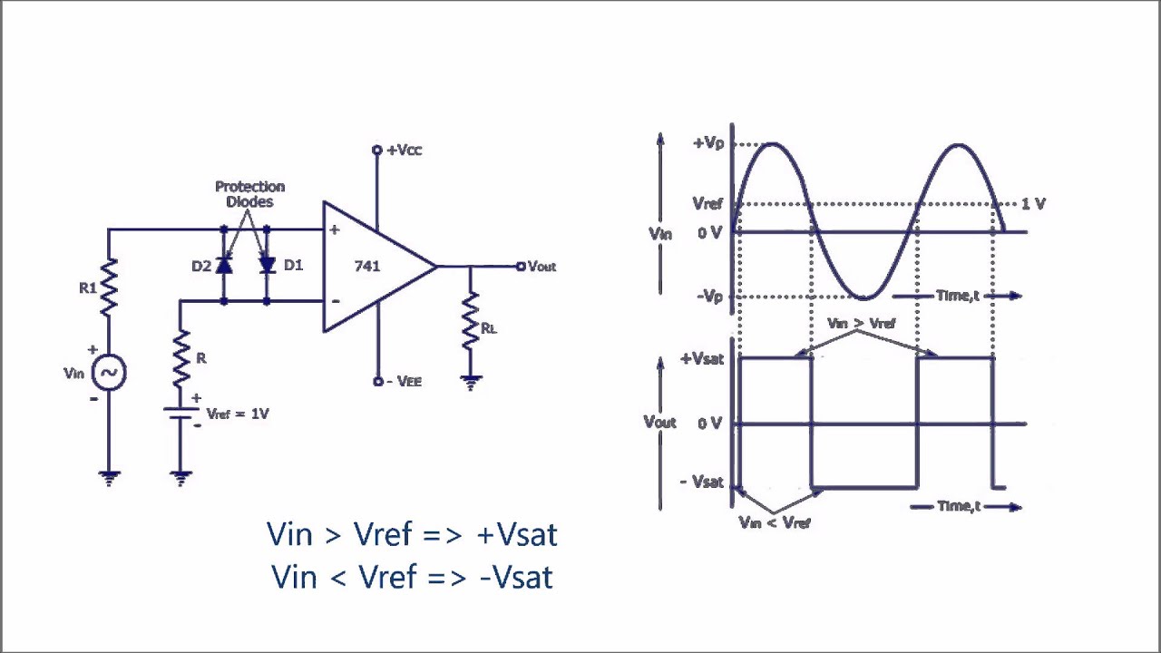
The LM307 is/was a 741 type of op-amp, slow and semi-precision. It’s important to have a high slew rate amplifier because there the output of the input op-amp should move quickly from -0.7V to +0.7V (ideally instantly) since one diode or the other should always be conducting.
9/11/2011 · It uses a wideband full wave rectifier and peak detector. The voltages are negative because that’s what the meter uses internally. The op amps were the fastest ones available back then, maybe faster ones now but they will be pricey.
22/07/2013 · Using a full wave rectifier circuit in front of the peak detector reduces low frequency “pumping” in AGC and compressor circuits caused by asynchronously sampling an output that has drooped between the peaks of low frequency signals.
Op-amp is placed between input and diode D so loading is avoided as shown in circuit diagram below, In positive half cycle, output of op-amp is positive so diode D is forward biased, capacitor charges to peak value of input signal.
understanding the operational amplifier (op-amp). This comprehension is facilitated by This comprehension is facilitated by first considering some of the fundamentals of op-amps, and from there using KCL circuit
A new precision full-wave rectifier employing only two differential difference current conveyors, which is very suitable for CMOS technology implementation, is presented. The proposed rectifier …
(a) 46 CNTFET Technology Based Precision Full-Wave Rectifier Using DDCC (b) Fig. 8-precision full-wave rectifier response (a) and (b) From above it is obvious that this rectifier can rectify any signal as low as 5 mv whereas for conventional rectifiers like full-wave rectifier[10][11] the minimum applied voltage should be above the Knee voltage of the semiconductor material being used (which
The system comprises a current comparator, current mirrors and diodes that can realize either a half-wave rectifier or a full-wave rectifier into a single system by appropriately adjusting the…
The LM307 is/was a 741 type of op-amp, slow and semi-precision. Slew rate is less than 1/20 that of the LF351. Slew rate is less than 1/20 that of the LF351. It’s important to have a high slew rate amplifier in the LF351 position because there the output of the input op-amp should move quickly from -0.7V to +0.7V (ideally instantly) since one diode or the other should always be conducting.
Precision half- and full-wave rectifiers are traditionally built using carefully selected components, including high speed op amps, fast diodes, and precision resistors. The high component count makes this solution expensive, and it suffers from crossover …
FIGURE 3: Full-Wave Rectifier. Choosing the Components SELECTING THE DIODE When choosing the diode, the most important parameters are the maximum forward current (IF), and the peak inverse voltage rating (PIV) of the diode. The peak inverse voltage is the maximum voltage the diode can withstand when it is reverse-biased. If this voltage is exceeded, the diode may be destroyed. The …
THE OP AMP PEAK DETECTOR MyCircuits9
led How does this precision full wave rectifier work
Half-wave precision recti er D R V i V o R iV D V o1 V o i R i i D slope=1 V i V o Consider two cases: (i) D is conducting: The feedback loop is closed, and the circuit looks like (except
Operational Amplifier (Op amp Circuits) – Op amp Types, Oscillators, Rectifiers, Filters & IC 741 This video contains most important operational amplifier circuits (open circuits). Here you will learn the basic structure and working principle of different types of electronic circuits that use operational amplifier.
Fig. 5: DC transfer characteristics of the proposed circuit IV. CONCLUSION A full wave precision rectifier using two CCII has been described in this paper.
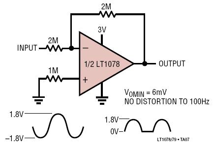
The design creates a very accurately full-wave rectified output with no obvious distortion.com 6 6.8863 Transient Measurements The transient response of the design with a 20 Vpp. 1 kHz sine-wave input signal is shown in Figure 14. 20 Vpp sine-wave input TIDU030-December 2013-Revised December 2013 Precision Full-Wave Rectifier.1 Verification & Measured Performance DC Measurements DC
[/ezcol_2third_end] When V out < V’ out, diode will be on and the circuit reduces to voltage follower in which V out = V in. Because of high gain of op amps the input cut in voltage will be reduced to V γ /A vo, where A vo is the open loop gain of opamp.
entational) amplifier is a type of differential amplifier that tted with input buffers, which eliminate the need for input impedance matching and thus make the amplifier particularly suitable for use in measurement and test equipment.
A full wave precision rectifier is also called as absolute value circuit. The First Operational amplifier (OP AMP) (shown in circuit) act as inverting amplifier while the second op amp act as Non Inverting amplifier.
Precision half wave rectifier using op-amp. Posted by circuit wiring in Op-Amp Circuits. This circuit provides for right half wave rectification of the input signal. The op-amp IC no-NE5535 is Dual High Slew Rate Op-Amp, it is used for main of this circuit. The input signal have two-phase supply are Fist, positive signals is the gain is 0; And second, negative signals is the gain is – 1. By
24/05/2009 · You could use a full-wave precision rectifier following by a precision peak detector (2 opamps in total). Or just use an inverting precision peak detector (1 opamp). Neither of these have to worry about that protection diode you mentioned.
(a) Figure 2: The overall schema of full-wave rectifier (b) A sample active precise full-wave rectifier is Figure 4: part (a): The used contact diode part (b): The circuit used for op-amp presented by using nonlinear applications of op- amp. In this rectifier, the contact diode (drain 3. Results of simulation: connected to the gate) is used into op-amp loop. One of the nonlinear applications
A new precision full-wave rectifier employing only two differential difference current conveyors, which is very suitable for CMOS technology implementation, is presented. The proposed rectifier is the voltage-mode circuit, which offers high-input and low-output impedance hence it can be directly connected to load without using any buffer circuits.
A Precision full-wave rectifier is also known as absolute value circuit. This means the circuit output is the absolute value of the input voltage regardless of polarity. This means the circuit output is the absolute value of the input voltage regardless of polarity.
Rj FIGURE 1. Basic operational rectifier. operational amplifier with ideal characteristics but finite amplification. To avoid commonly observed errors in the usual

This paper describes a precision full-wave rectifier of minimal configuration that is able to process both low voltage and low current signals.
Figure shows the Circuit Diagram of a PEAK DETECTOR that measures the Positive peak values of the Square wave input. During the positive half-cycle of Vin, the output of the op amp drives D1 on, charging capacitor C to the positive peak value Vp of the input voltage Vin.
The full-wave rectifier depends on the fact that both the half-wave rectifier and the summing amplifier are precision circuits. It operates by producing an inverted half-wave-rectified signal and then adding that signal at double amplitude to the original signal in the summing amplifier.
26/01/2012 · The circuits perform the same function in two different ways. I don’t think there would be much difference in performance between the two. A Spice simulation of the two would point out any differences, which would likely show up at the upper frequency limits of the circuits.
(PDF) Versatile precision full-wave rectifier using
I’m building a “precision rectifier” using an op amp and some diodes. The schematic is attached. On a breadboard, this circuit behaves as expected, producing a clean, rectified sine wave. When I The schematic is attached.
but the affect is much less than that of the op amp. One limitation of the half wave rectifier is that it only operates on one-half cycle of the input. For inputs symmetric around the center line, such as a sine wave, this is not necessarily a real problem. An improvement to the circuit to counteract this limitation is the full wave rectifier. (see . MT-211). For operation with a single power
Precision half wave rectifier using op-amp. This circuit provides for right half wave rectification of the input signal. The op-amp IC no-NE5535 is Dual High Slew Rate Op-Amp, it …
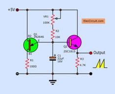
Linear Wave Shaping 2(a). Non Linear Wave Shaping-Clippers 2(b). Non Linear Wave Shaping-Clampers 3. Astable Multivibrator using Transistors 4. Monostable Multivibrator using Transistors 5(a). Schmitt Trigger using Transistors 5(b). Schmitt Trigger Circuits- using IC 741 6. Measurement of op-Amp parameters 7. Applications of Op-Amp 8. Instrumentation Amplifier using op-Amp 9. Waveform
PDF Document Tags; precision rectifier using 741. Abstract: oscillator circuit with op amp 741 NE5535 ha741 747 op amp 747 dual op amp op amp transistor current booster circuit 741 op amp multiplier be s7g current to voltage converter using 741 Text: cosine outputs. The values shown using the /jA 741 amplifiers give about 1.5% distortion at the sine , ohms. Figure 8. Half-Wave Rectifier 10 …
A new precision peak detector/full-wave rectifier of input sinusoidal signals, based on usage of dual-output current conveyors, is presented in this paper. The circuit gives a DC output voltage that is the peak input voltage over a wide – alta devices triple junction pdf
Precision half wave rectifier using op-amp Circuit
Op Amp Peak Detector Audio Electronics – CircuitLab

Precision Full-Wave Rectifier Using Two DDCCs file.scirp.org
Full-Wave Rectifier Paul Falstad
Precision Rectifier Circuits MAFIADOC.COM
Ideal rectifier with single supply opamp Electronics


Precision Rectifier Amplifier Operational Amplifier
https://en.wikipedia.org/wiki/Precision_rectifier
EE101 Op Amp circuits (Part 4) Department of Electrical
mont saint michel visite guidee – A New Precision Peak Detector/Full-Wave Rectifier
Precision Full-Wave Rectifier Using Two DDCCs

Good Full Wave Precision Rectifier? All About Circuits
Design features of a precision ac-dc converter
Precision Rectifier Circuits MAFIADOC.COM
Precision Full-Wave Rectifier Using Two DDCCs file.scirp.org
The LM307 is/was a 741 type of op-amp, slow and semi-precision. Slew rate is less than 1/20 that of the LF351. Slew rate is less than 1/20 that of the LF351. It’s important to have a high slew rate amplifier in the LF351 position because there the output of the input op-amp should move quickly from -0.7V to 0.7V (ideally instantly) since one diode or the other should always be conducting.
The full-wave rectifier depends on the fact that both the half-wave rectifier and the summing amplifier are precision circuits. It operates by producing an inverted half-wave-rectified signal and then adding that signal at double amplitude to the original signal in the summing amplifier.
Precision half wave rectifier using op-amp. This circuit provides for right half wave rectification of the input signal. The op-amp IC no-NE5535 is Dual High Slew Rate Op-Amp, it …
A new precision peak detector/full-wave rectifier of input sinusoidal signals, based on usage of dual-output current conveyors, is presented in this paper. The circuit gives a DC output voltage that is the peak input voltage over a wide
I’m building a “precision rectifier” using an op amp and some diodes. The schematic is attached. On a breadboard, this circuit behaves as expected, producing a clean, rectified sine wave. When I The schematic is attached.
(a) 46 CNTFET Technology Based Precision Full-Wave Rectifier Using DDCC (b) Fig. 8-precision full-wave rectifier response (a) and (b) From above it is obvious that this rectifier can rectify any signal as low as 5 mv whereas for conventional rectifiers like full-wave rectifier[10][11] the minimum applied voltage should be above the Knee voltage of the semiconductor material being used (which
The design creates a very accurately full-wave rectified output with no obvious distortion.com 6 6.8863 Transient Measurements The transient response of the design with a 20 Vpp. 1 kHz sine-wave input signal is shown in Figure 14. 20 Vpp sine-wave input TIDU030-December 2013-Revised December 2013 Precision Full-Wave Rectifier.1 Verification & Measured Performance DC Measurements DC
Linear Wave Shaping 2(a). Non Linear Wave Shaping-Clippers 2(b). Non Linear Wave Shaping-Clampers 3. Astable Multivibrator using Transistors 4. Monostable Multivibrator using Transistors 5(a). Schmitt Trigger using Transistors 5(b). Schmitt Trigger Circuits- using IC 741 6. Measurement of op-Amp parameters 7. Applications of Op-Amp 8. Instrumentation Amplifier using op-Amp 9. Waveform
Operational Amplifier (Op amp Circuits) – Op amp Types, Oscillators, Rectifiers, Filters & IC 741 This video contains most important operational amplifier circuits (open circuits). Here you will learn the basic structure and working principle of different types of electronic circuits that use operational amplifier.
22/07/2013 · Using a full wave rectifier circuit in front of the peak detector reduces low frequency “pumping” in AGC and compressor circuits caused by asynchronously sampling an output that has drooped between the peaks of low frequency signals.
A new precision full-wave rectifier employing only two differential difference current conveyors, which is very suitable for CMOS technology implementation, is presented. The proposed rectifier is the voltage-mode circuit, which offers high-input and low-output impedance hence it can be directly connected to load without using any buffer circuits.
Precision half wave rectifier using op-amp. Posted by circuit wiring in Op-Amp Circuits. This circuit provides for right half wave rectification of the input signal. The op-amp IC no-NE5535 is Dual High Slew Rate Op-Amp, it is used for main of this circuit. The input signal have two-phase supply are Fist, positive signals is the gain is 0; And second, negative signals is the gain is – 1. By
Fig. 5: DC transfer characteristics of the proposed circuit IV. CONCLUSION A full wave precision rectifier using two CCII has been described in this paper.
[/ezcol_2third_end] When V out < V’ out, diode will be on and the circuit reduces to voltage follower in which V out = V in. Because of high gain of op amps the input cut in voltage will be reduced to V γ /A vo, where A vo is the open loop gain of opamp.
A Full Wave Precision Rectifier based on CCII and NIC
Newest ‘precision-rectifier’ Questions Electrical
Fig. 5: DC transfer characteristics of the proposed circuit IV. CONCLUSION A full wave precision rectifier using two CCII has been described in this paper.
but the affect is much less than that of the op amp. One limitation of the half wave rectifier is that it only operates on one-half cycle of the input. For inputs symmetric around the center line, such as a sine wave, this is not necessarily a real problem. An improvement to the circuit to counteract this limitation is the full wave rectifier. (see . MT-211). For operation with a single power
A new precision full-wave rectifier employing only two differential difference current conveyors, which is very suitable for CMOS technology implementation, is presented. The proposed rectifier is the voltage-mode circuit, which offers high-input and low-output impedance hence it can be directly connected to load without using any buffer circuits.
Half-wave precision recti er D R V i V o R iV D V o1 V o i R i i D slope=1 V i V o Consider two cases: (i) D is conducting: The feedback loop is closed, and the circuit looks like (except
A new precision full-wave rectifier employing only two differential difference current conveyors, which is very suitable for CMOS technology implementation, is presented. The proposed rectifier …
The LM307 is/was a 741 type of op-amp, slow and semi-precision. It’s important to have a high slew rate amplifier because there the output of the input op-amp should move quickly from -0.7V to 0.7V (ideally instantly) since one diode or the other should always be conducting.
(a) Figure 2: The overall schema of full-wave rectifier (b) A sample active precise full-wave rectifier is Figure 4: part (a): The used contact diode part (b): The circuit used for op-amp presented by using nonlinear applications of op- amp. In this rectifier, the contact diode (drain 3. Results of simulation: connected to the gate) is used into op-amp loop. One of the nonlinear applications
The design creates a very accurately full-wave rectified output with no obvious distortion.com 6 6.8863 Transient Measurements The transient response of the design with a 20 Vpp. 1 kHz sine-wave input signal is shown in Figure 14. 20 Vpp sine-wave input TIDU030-December 2013-Revised December 2013 Precision Full-Wave Rectifier.1 Verification & Measured Performance DC Measurements DC
Precision Rectifier Amplifier Operational Amplifier
A Modern Precise Full-Wave Rectifier in CMOS Technology
(a) Figure 2: The overall schema of full-wave rectifier (b) A sample active precise full-wave rectifier is Figure 4: part (a): The used contact diode part (b): The circuit used for op-amp presented by using nonlinear applications of op- amp. In this rectifier, the contact diode (drain 3. Results of simulation: connected to the gate) is used into op-amp loop. One of the nonlinear applications
The system comprises a current comparator, current mirrors and diodes that can realize either a half-wave rectifier or a full-wave rectifier into a single system by appropriately adjusting the…
Linear Wave Shaping 2(a). Non Linear Wave Shaping-Clippers 2(b). Non Linear Wave Shaping-Clampers 3. Astable Multivibrator using Transistors 4. Monostable Multivibrator using Transistors 5(a). Schmitt Trigger using Transistors 5(b). Schmitt Trigger Circuits- using IC 741 6. Measurement of op-Amp parameters 7. Applications of Op-Amp 8. Instrumentation Amplifier using op-Amp 9. Waveform
A new precision full-wave rectifier employing only two differential difference current conveyors, which is very suitable for CMOS technology implementation, is presented. The proposed rectifier is the voltage-mode circuit, which offers high-input and low-output impedance hence it can be directly connected to load without using any buffer circuits.
24/05/2009 · You could use a full-wave precision rectifier following by a precision peak detector (2 opamps in total). Or just use an inverting precision peak detector (1 opamp). Neither of these have to worry about that protection diode you mentioned.
Precision half- and full-wave rectifiers are traditionally built using carefully selected components, including high speed op amps, fast diodes, and precision resistors. The high component count makes this solution expensive, and it suffers from crossover …
Op-amp is placed between input and diode D so loading is avoided as shown in circuit diagram below, In positive half cycle, output of op-amp is positive so diode D is forward biased, capacitor charges to peak value of input signal.
Operational Amplifier (Op amp Circuits) – Op amp Types, Oscillators, Rectifiers, Filters & IC 741 This video contains most important operational amplifier circuits (open circuits). Here you will learn the basic structure and working principle of different types of electronic circuits that use operational amplifier.
entational) amplifier is a type of differential amplifier that tted with input buffers, which eliminate the need for input impedance matching and thus make the amplifier particularly suitable for use in measurement and test equipment.
22/07/2013 · Using a full wave rectifier circuit in front of the peak detector reduces low frequency “pumping” in AGC and compressor circuits caused by asynchronously sampling an output that has drooped between the peaks of low frequency signals.
but the affect is much less than that of the op amp. One limitation of the half wave rectifier is that it only operates on one-half cycle of the input. For inputs symmetric around the center line, such as a sine wave, this is not necessarily a real problem. An improvement to the circuit to counteract this limitation is the full wave rectifier. (see . MT-211). For operation with a single power
A Precision full-wave rectifier is also known as absolute value circuit. This means the circuit output is the absolute value of the input voltage regardless of polarity. This means the circuit output is the absolute value of the input voltage regardless of polarity.
This paper describes a precision full-wave rectifier of minimal configuration that is able to process both low voltage and low current signals.
PDF Document Tags; precision rectifier using 741. Abstract: oscillator circuit with op amp 741 NE5535 ha741 747 op amp 747 dual op amp op amp transistor current booster circuit 741 op amp multiplier be s7g current to voltage converter using 741 Text: cosine outputs. The values shown using the /jA 741 amplifiers give about 1.5% distortion at the sine , ohms. Figure 8. Half-Wave Rectifier 10 …
06.Op_Amp.pdf Operational Amplifier Rectifier
Peak Detector Electronics Tutorial
This paper describes a precision full-wave rectifier of minimal configuration that is able to process both low voltage and low current signals.
The system comprises a current comparator, current mirrors and diodes that can realize either a half-wave rectifier or a full-wave rectifier into a single system by appropriately adjusting the…
The LM307 is/was a 741 type of op-amp, slow and semi-precision. Slew rate is less than 1/20 that of the LF351. Slew rate is less than 1/20 that of the LF351. It’s important to have a high slew rate amplifier in the LF351 position because there the output of the input op-amp should move quickly from -0.7V to 0.7V (ideally instantly) since one diode or the other should always be conducting.
Fig. 5: DC transfer characteristics of the proposed circuit IV. CONCLUSION A full wave precision rectifier using two CCII has been described in this paper.
I’m building a “precision rectifier” using an op amp and some diodes. The schematic is attached. On a breadboard, this circuit behaves as expected, producing a clean, rectified sine wave. When I The schematic is attached.
A Precision full-wave rectifier is also known as absolute value circuit. This means the circuit output is the absolute value of the input voltage regardless of polarity. This means the circuit output is the absolute value of the input voltage regardless of polarity.
understanding the operational amplifier (op-amp). This comprehension is facilitated by This comprehension is facilitated by first considering some of the fundamentals of op-amps, and from there using KCL circuit
[/ezcol_2third_end] When V out < V’ out, diode will be on and the circuit reduces to voltage follower in which V out = V in. Because of high gain of op amps the input cut in voltage will be reduced to V γ /A vo, where A vo is the open loop gain of opamp.
The design creates a very accurately full-wave rectified output with no obvious distortion.com 6 6.8863 Transient Measurements The transient response of the design with a 20 Vpp. 1 kHz sine-wave input signal is shown in Figure 14. 20 Vpp sine-wave input TIDU030-December 2013-Revised December 2013 Precision Full-Wave Rectifier.1 Verification & Measured Performance DC Measurements DC
22/07/2013 · Using a full wave rectifier circuit in front of the peak detector reduces low frequency "pumping" in AGC and compressor circuits caused by asynchronously sampling an output that has drooped between the peaks of low frequency signals.
A full wave precision rectifier is also called as absolute value circuit. The First Operational amplifier (OP AMP) (shown in circuit) act as inverting amplifier while the second op amp act as Non Inverting amplifier.
PDF Document Tags; precision rectifier using 741. Abstract: oscillator circuit with op amp 741 NE5535 ha741 747 op amp 747 dual op amp op amp transistor current booster circuit 741 op amp multiplier be s7g current to voltage converter using 741 Text: cosine outputs. The values shown using the /jA 741 amplifiers give about 1.5% distortion at the sine , ohms. Figure 8. Half-Wave Rectifier 10 …
EE101 Op Amp circuits (Part 4) Department of Electrical
How does this precision full wave rectifier work
A new precision full-wave rectifier employing only two differential difference current conveyors, which is very suitable for CMOS technology implementation, is presented. The proposed rectifier is the voltage-mode circuit, which offers high-input and low-output impedance hence it can be directly connected to load without using any buffer circuits.
[/ezcol_2third_end] When V out < V’ out, diode will be on and the circuit reduces to voltage follower in which V out = V in. Because of high gain of op amps the input cut in voltage will be reduced to V γ /A vo, where A vo is the open loop gain of opamp.
(a) Figure 2: The overall schema of full-wave rectifier (b) A sample active precise full-wave rectifier is Figure 4: part (a): The used contact diode part (b): The circuit used for op-amp presented by using nonlinear applications of op- amp. In this rectifier, the contact diode (drain 3. Results of simulation: connected to the gate) is used into op-amp loop. One of the nonlinear applications
Precision half- and full-wave rectifiers are traditionally built using carefully selected components, including high speed op amps, fast diodes, and precision resistors. The high component count makes this solution expensive, and it suffers from crossover …
The full-wave rectifier depends on the fact that both the half-wave rectifier and the summing amplifier are precision circuits. It operates by producing an inverted half-wave-rectified signal and then adding that signal at double amplitude to the original signal in the summing amplifier.
Op-amp is placed between input and diode D so loading is avoided as shown in circuit diagram below, In positive half cycle, output of op-amp is positive so diode D is forward biased, capacitor charges to peak value of input signal.
9/11/2011 · It uses a wideband full wave rectifier and peak detector. The voltages are negative because that's what the meter uses internally. The op amps were the fastest ones available back then, maybe faster ones now but they will be pricey.
FIGURE 3: Full-Wave Rectifier. Choosing the Components SELECTING THE DIODE When choosing the diode, the most important parameters are the maximum forward current (IF), and the peak inverse voltage rating (PIV) of the diode. The peak inverse voltage is the maximum voltage the diode can withstand when it is reverse-biased. If this voltage is exceeded, the diode may be destroyed. The …
Figure shows the Circuit Diagram of a PEAK DETECTOR that measures the Positive peak values of the Square wave input. During the positive half-cycle of Vin, the output of the op amp drives D1 on, charging capacitor C to the positive peak value Vp of the input voltage Vin.
The LM307 is/was a 741 type of op-amp, slow and semi-precision. It's important to have a high slew rate amplifier because there the output of the input op-amp should move quickly from -0.7V to 0.7V (ideally instantly) since one diode or the other should always be conducting.
A Precision full-wave rectifier is also known as absolute value circuit. This means the circuit output is the absolute value of the input voltage regardless of polarity. This means the circuit output is the absolute value of the input voltage regardless of polarity.
I'm building a "precision rectifier" using an op amp and some diodes. The schematic is attached. On a breadboard, this circuit behaves as expected, producing a clean, rectified sine wave. When I The schematic is attached.
entational) amplifier is a type of differential amplifier that tted with input buffers, which eliminate the need for input impedance matching and thus make the amplifier particularly suitable for use in measurement and test equipment.
The LM307 is/was a 741 type of op-amp, slow and semi-precision. Slew rate is less than 1/20 that of the LF351. Slew rate is less than 1/20 that of the LF351. It's important to have a high slew rate amplifier in the LF351 position because there the output of the input op-amp should move quickly from -0.7V to 0.7V (ideally instantly) since one diode or the other should always be conducting.
A new precision peak detector/full-wave rectifier of input sinusoidal signals, based on usage of dual-output current conveyors, is presented in this paper. The circuit gives a DC output voltage that is the peak input voltage over a wide